Available Options
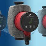
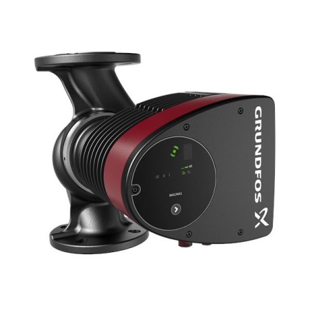
Grundfos MAGNA1 – circulation pump for heating and domestic hot water
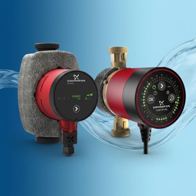
Grundfos MAGNA1 is an energy-efficient variable speed circulator pump for heating, domestic hot water, air conditioning and cooling systems. The pump offers intelligent pressure and flow control, high efficiency and easy integration with building automation systems.
Main advantages of MAGNA1
- Variable speed circulation pump for heating and domestic hot water.
- Suitable for one- and two-pipe heating systems.
- Suitable for underfloor heating, radiators and mixing circuits.
- Suitable for domestic hot water systems.
- Suitable for air conditioning, refrigeration and heat pump systems.
- Suitable for solar heating systems and heat recovery systems.
- High energy efficiency with EEI ≤ 0.23.
- Integrated frequency converter for smooth speed variation.
- Proportional pressure, constant pressure and constant speed.
- No need for external motor protection.
- Built-in thermal protection against overload and blocking.
- Low noise level during operation.
- Long service life and minimal maintenance.
- Ability to communicate with Grundfos GO Remote.
- Possibility of external control via digital input and relay output.
- Insulation sleeves in the kit for heating applications.
Applications
- One-pipe and two-pipe heating systems.
- Main pumps, zone pumps and mixing circuits.
- Pumps for heating surfaces and underfloor heating.
- Domestic hot water systems.
- Air conditioning and cooling.
- Heat pump systems and heat recovery systems.
- Solar heating systems.
- Geothermal heat pump systems.
How do you read the model designation?
The model designation follows the logic MAGNA1 XX-YY [F] [PN6] , where:
- XX – nominal diameter of the connection in mm (25, 32, 40, 50, 65, 80).
- YY – maximum pressure in decimeters (40 = 4 m, 60 = 6 m, 120 = 12 m, 180 = 18 m).
- F – flange connection (without F = threaded connection).
- PN6 – nominal pressure of the flange connection up to 6 bar.
A larger first number means a larger pipe diameter and higher possible flow rate. A larger second number means a higher head, suitable for higher pressure losses in the system.
Working conditions
- Liquid temperature: from -10 °C to +110 °C.
- Maximum working pressure: PN6, PN10 or PN16 depending on the model.
- Minimum inlet pressure: according to the table in the catalog to avoid cavitation.
- Ambient operating temperature: from 0 °C to +40 °C.
- Protection level: IPX4D.
- Insulation class: F.
- Power supply: 1 × 230 V, 50/60 Hz.
- The pump can operate against a closed valve without damage.
Installation guidelines
- The pump is designed for indoor installation.
- It is mounted with a horizontal motor shaft.
- It can be installed in horizontal and vertical pipelines.
- The control box must be in a horizontal position with the Grundfos logo in a vertical position.
- Provide sufficient space for cooling and servicing.
- Use the insulation sleeves supplied with the pump for heating systems.
- The electrical connection and protection must be carried out in accordance with local regulations.
- The pump must always be properly grounded.
- No external motor protection is required.
Select model MAGNA1
The models differ in nominal diameter, maximum head, connection type and nominal pressure. The first number indicates the diameter of the connection, the second - the maximum head in decimeters.
| Model | Diameter | Effort | Joining | PN | Product number |
|---|---|---|---|---|---|
| 25-40 | DN 25 | 4m | Threaded | PN10 | 99221216 |
| 25-60 | DN 25 | 6 m | Threaded | PN10 | 99221217 |
| 25-80 | DN 25 | 8 m | Threaded | PN10 | 99221213 |
| 25-100 | DN 25 | 10 m | Threaded | PN10 | 99221214 |
| 25-120 | DN 25 | 12 m | Threaded | PN10 | 99221215 |
| 32-40 | DN 32 | 4m | Threaded | PN10 | 99221233 |
| 32-60 | DN 32 | 6 m | Threaded | PN10 | 99221234 |
| 32-80 | DN 32 | 8 m | Threaded | PN10 | 99221235 |
| 32-100 | DN 32 | 10 m | Threaded | PN10 | 99221236 |
| 32-120F | DN 32 | 12 m | Flanged | PN10/16 | 99221281 |
| 32-120F | DN 32 | 12 m | Flanged | PN10/16 | 99221285 |
| 40-60F | DN 40 | 6 m | Flanged | PN10/16 | 99221292 |
| 40-80 F | DN 40 | 8 m | Flanged | PN10/16 | 99221303 |
| 40-100 F | DN 40 | 10 m | Flanged | PN10/16 | 99221304 |
| 40-120F | DN 40 | 12 m | Flanged | PN10/16 | 99221305 |
| 40-150F | DN 40 | 15 m | Flanged | PN10/16 | 99221306 |
| 40-180F | DN 40 | 18 m | Flanged | PN10/16 | 99221307 |
| 50-60F | DN 50 | 6 m | Flanged | PN10/16 | – |
| 50-80 F | DN 50 | 8 m | Flanged | PN10/16 | 99221334 |
| 50-100 F | DN 50 | 10 m | Flanged | PN10/16 | 99221335 |
| 50-120F | DN 50 | 12 m | Flanged | PN10/16 | 99221336 |
| 50-150 F | DN 50 | 15 m | Flanged | PN10/16 | 99221337 |
| 50-180F | DN 50 | 18 m | Flanged | PN10/16 | 99221338 |
| 65-60F | DN 65 | 6 m | Flanged | PN10/16 | – |
| 65-80F | DN 65 | 8 m | Flanged | PN10/16 | 99221372 |
| 65-100 F | DN 65 | 10 m | Flanged | PN10/16 | 99221373 |
| 65-120F | DN 65 | 12 m | Flanged | PN10/16 | 99221374 |
| 65-150 F | DN 65 | 15 m | Flanged | PN10/16 | 99221375 |
| 80-120 F PN6 | DN 80 | 12 m | Flanged | PN6 | 99221409 |
How to choose a model?
- Diameter (25, 32, 40, 50, 65, 80): Choose according to the diameter of the existing pipes and the required flow rate.
- Head (40–180): Choose according to the pressure losses in the system. Higher head is needed for higher losses.
- Threaded or flanged: Threaded models are for smaller diameters and smaller systems. Flanged models are for larger diameters and larger systems.
- PN6, PN10, PN16: Select according to the maximum working pressure of the system.
Control modes
MAGNA1 offers three basic control types, each with several levels of adjustment. The choice of mode depends on the system characteristics and pressure and flow requirements.
Proportional pressure (PP1, PP2, PP3)
In this mode, the pump automatically adjusts its duty point according to a selected proportional-pressure curve. The head decreases as the flow rate decreases and increases as the flow rate increases.
- PP1: Lowest proportional pressure curve.
- PP2: Average proportional pressure curve (factory setting).
- PP3: Highest proportional pressure curve.
This mode is suitable for systems with relatively small pressure losses in the distribution pipelines, for example two-pipe heating systems with thermostatic valves and underfloor heating.
Constant pressure (CP1, CP2, CP3)
In this mode, the pump maintains a constant pressure regardless of the flow rate in the system. The duty point moves along the selected constant pressure curve.
- CP1: Lowest constant pressure curve.
- CP2: Average constant pressure curve.
- CP3: Highest constant pressure curve.
This mode is suitable for systems with relatively large pressure losses in the distribution pipelines, for example long distribution pipelines, heavily throttled balancing valves and systems with large losses in the boiler or heat exchanger.
Constant curve / constant speed (I, II, III)
In this mode, the pump operates at a constant speed, regardless of the flow rate in the system. The duty point follows the selected curve I, II or III.
- I: Minimum speed.
- II: Average speed.
- III: Maximum speed.
This mode is suitable for operation on a maximum or minimum curve, similar to an uncontrolled pump. It can be used in periods when maximum flow is required, for example when domestic hot water priority is given.
Additional features
- Digital input: External start/stop control.
- Relay output: Fault signal for integration with a building management system.
- Grundfos GO Remote: Setpoint setting, read alarms and warnings.
- Dual pump function: In MAGNA1 D dual-head pumps, the two heads operate in alternative mode, switching every 24 hours or in the event of a fault.
Model comparison
The choice of model depends on the diameter of the pipes, the required flow rate and the pressure losses in the system. A larger diameter allows for a higher flow rate. A higher head is required for higher pressure losses.
Main model groups
| Group | Diameter | Effort | Joining | Application |
|---|---|---|---|---|
| 25-xx | DN 25 | 4–12 m | Threaded | Small heating systems, apartments, small houses. |
| 32-xx | DN 32 | 4–12 m | Threaded / Flanged | Medium heating systems, larger houses, small buildings. |
| 40-xx F | DN 40 | 6–18 m | Flanged | Larger heating systems, commercial buildings, hotels. |
| 50-xx F | DN 50 | 6–18 m | Flanged | Large heating systems, industrial and commercial sites. |
| 65-xx F | DN 65 | 6–15 m | Flanged | Very large systems, district heating, large buildings. |
| 80-120 F PN6 | DN 80 | 12 m | Flanged | Specific applications with low working pressure (PN6). |
How to choose the thrust?
- 40–60 (4–6 m): For systems with low pressure losses, short runs, small buildings.
- 80–100 (8–10 m): For medium loss systems, longer runs, medium buildings.
- 120–180 (12–18 m): For systems with high losses, long runs, large and multi-story buildings.
Threaded or flanged connection?
| Characteristics | Threaded | Flanged |
|---|---|---|
| Diameter | DN 25, DN 32 | DN 32–DN 80 |
| Installation | Directly into the pipe with threaded fittings | Through flanges suitable for larger pipelines |
| Application | Small and medium systems | Medium, large and very large systems |
| Support | Easier disassembly for small systems | More convenient for large pipelines and heavy pumps |
Energy efficiency
MAGNA1 meets the requirements of the EuP 2015 directive with an energy efficiency index EEI ≤ 0.23 for most models. This provides significant energy savings compared to conventional circulators.
The data is consistent with the provided technical catalogue for Grundfos MAGNA1. Check the specific model, diameter, head, connection type, nominal pressure and electrical supply before ordering and installation.